BRAKE TESTING WITH VBOX - EQUIPMENT
Most braking departments around the world use the VBOX 100Hz GNSS logger for measurement of braking distance, with the addition of an IMU05 system to counteract the lever arm effect for speed triggered measurements, or in areas of low GNSS visibility.
The cost effective 25Hz VBOX Touch GNSS data logger can also be used for braking measurements (Accuracies: VBOX 4 ±1.8cm, VBOX Touch ±10cm).
In addition, the new VBOX Touch when used in conjunction with the RLACS282 Load Cell and RLVBMIM Mini Input Module has a dedicated brake test plug-in providing cm accuracte brake testing.
Do you need a complete brake test package?
The Racelogic VBOX and VBOX Test Suite software provides the ideal solution. VBOX Australia can also provide complete ready to go systems including the VBOX, Load cell, strain gauge amplifier and pressure transducer all calibrated and ready to use.
What equipment do I need?
A typical VBOX setup for measuring Braking distance from a trigger is:
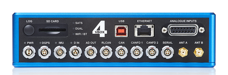
1) - VBOX 4
The VBOX 4, VBOX 4 dual antenna or VBOX 4 ADAS 100Hz RTK enabled data logger has the ability to utilise data from a RACELOGIC IMU to improve all parameters measured in real-time - improving accuracy and noise levels, and enhancing the dynamic response to velocity.
IMU integration also combats satellite drop-out for up to 10 seconds without lock (optional).
The VBOX 4 - Dual antenna 100Hz data logger is a twin antenna logger and can accuratly measure Slip/Pitch or Slip/Roll. This also gives the abiltiy to measure Yaw angles required for ADR 31/xx, ECE R13-H.
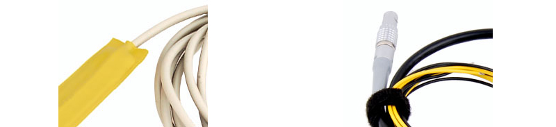
2) - Brake Trigger
A Brake Trigger provides precise measurement of brake pedal application during VBOX brake stop tests
The frequency at which the trigger event is recorded is dependent on the model of VBOX in use.
There are 2 options that will meet Statutory Requirements.
However, The VBOX Test Suite Software has the ability to allow a brake test to start from a CAN Channel. This means that - for example - a Pedal Effort of 5N can be used as the trigger for the start of the test. This removes the need for the physical trigger shown above and reduces the amount of equipment needed.
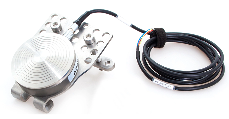
3) - Load Cell/s
For vehicle testing a single load cell is required which is mounted to the brake pedal.
In the case of Motorcycle testing 2 load cells are required, one for Foot (usually 1000N) and one for Hand (usually 500N).
The Racelogic RLACS282 pedal effort load cell shown below has a built in Strain Gauge Amplifier (SGA) and therefore does not require an external SGA, again simplifying the setup.
In the case of Motorcycel Brake testing, other load cells - such as button type - can be used with a Strain Gauge Amplifier.
4) - Strain Gauge Amplifier
VBOX Australia can provide a fully calibrated load cell and Strain Gaugue amplifier to complement the VBOX system. Not required if using the Racelogic Pedal Force Sensor (RLACS282).
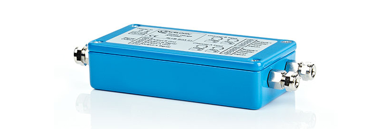
5) - Mini Input Module (MIM)
The MIM is used either as the input for the Load Cell and/or for the provision of K-Type Thermocouple inputs for pad temperatures. The MIM also has 8 analogue input channels and can be used for various sensors such as Brake pressure Transducers.

VBOX TOUCH Brake test solution:
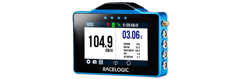
1) - VBOX TOUCH
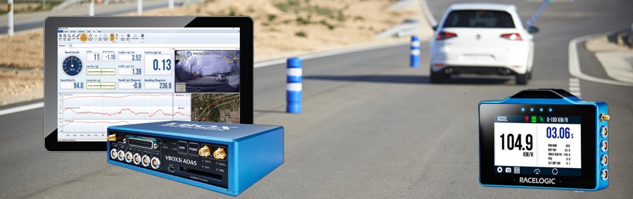
Featuring a 4.3” colour touchscreen, 25 Hz GNSS receiver and the ability to run multiple applications on the same hardware, the VBOX Touch is our most versatile data logger yet.
You can instantly see test results on the large, daylight readable touchscreen or if you would like to analyse your data in more detail, you can do so using dedicated plugins and visual aids such as charts, graphs and tables in VBOX Test Suite; our user-friendly, intuitive data analysis software.
2) - Brake Test App
This app uses a Pedal Force Sensor (RLACS282) connected to the VBOX Touch via a Mini Input Module (MIM01) to measure stopping distance from a nominated pedal force to zero.
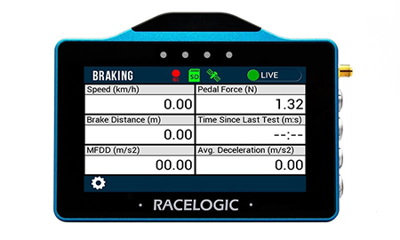
The user can specify the pedal force at which the test should start, as well as a minimum speed threshold at which the test will start. The screen displays the current vehicle speed, the current pedal force, the braking distance, the MFDD and the average deceleration of the last completed brake stop. The results from each brake stop are automatically recorded to a text file on the SD card, along with a .vbo file that contains all the VBOX data required for post-processing using the ‘Trigger’ plugin in VBOX Test suite.
To use this app, the Mini Input Module will need the configuration file for VBOX Touch.